For the next few paragraphs, please refer to the following picture, which is a clear, understandable example of a punch down block:

Those grey things in the middle are termination points for single wires. When you deal with punch down blocks, you deal in pairs of wires, and you get one wire to one grey clip. Pretend there is an imaginary line down the middle of that patch panel, because the pairs on the left are separate from the pairs on the right. If you number a line going across, 1 2 3 4, 1 and 2 are a pair, 3 and 4 are an entirely different pair. In the picture, you can tell, because of the numbering scheme they've used. There are 4 clips for a pair, but only 2 clips are wired in the beginning. Each pair is numbered, so the phone company can say "Turn on pair 3044".
Now, at our building, the phone company's lines are on the right side of the wall. On the left side of the wall is another huge array of punchdown blocks. These are for the "house wiring". When they built the building, they pre-ran hundreds of pairs of wires to each floor from this room, so that they wouldn't have to redo it every time someone ordered a T1. Each wire to each floor is terminated to a pair on the left side of the wall in exactly the same manner as the one on the right (including leaving one set empty).
To connect the two sides, you run a twisted pair of wires (it looks like you took a section of cat5, stripped off the sheathing, and just used one set of wires) from the right side of the wall (from the pair of grey clips we left open on #3044) to the left side of the wall (say #514, the 14th pair to the 5th floor, again using the empty grey clips). If you look again at that picture, you can see 3043 has been wired across, because all 4 wires are clipped in, but 3044 has not, since only the rightmost clips have wires.
At this point, you have two wires coming in from the phone company to the punch down blocks on the right. Then you've got wires connecting those punch down blocks to the "house wiring" punchdown blocks on the left. Then you've got vertical wiring up to the floor that the wire ends at.
In the comms closet on that floor (also known as the IDF, or intermediate distribution facility), you have a very similar situation. On the right hand side, you've got the punch down block where the vertical cabling from the MDF terminates, and on the left, you've got a punch down block where the actual wires that end up in your office are terminated. You use another twisted pair of wires to connect the two sides, and at that point, the wire that ends up in your office is connected directly to the phone company, albeit through several punch down blocks and lots of wire.
Now, when it comes into your office, hopefully someone has had the courtesy to install a patch panel for you. The patch panel looks like this on the front:
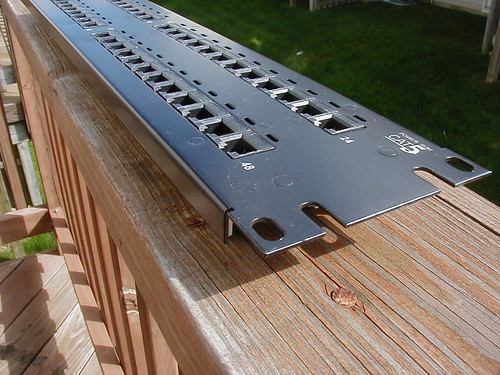
and this on the back:
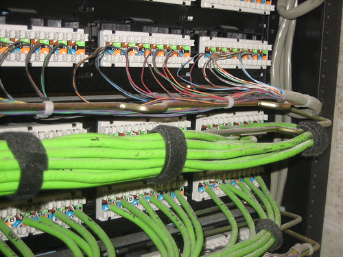
As you can tell from the photo on the back, wires are typically matched up color for color when it comes to straight CAT5 cables. When it comes to things like wiring T1s, you're only using two wires, so as long as you remember which one goes to what wire, you're ok.
So, i review, we've got phone company wires coming in, and terminated in the MDF. They're connected across to the house wiring, which is run vertically to the IDF, and from the IDF, it goes to your space. All of this is accomplished with those magic little grey clips.
Now, if only the wires would go in there. It turns out that there's a trick. Or a tool, really, called a punch down tool (creative, eh?). The cheapest punch down tool I've ever seen is a buck. It'll work in a pinch, but the one you want is here:
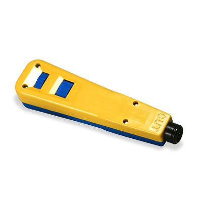
The way you use it is to arrange the wire you want to punch down against the metal clip. There's a very thin slit in the clip where the wire will end up. Press the tip of the punch down tool against the clip, and push. The spring loaded mechanism (in the expensive tool) or your elbow grease (in $.99 model) will push the wire to the bottom of the slit, and in the process, scrap away the plastic or teflon sheathing on the wire, allowing the metals to make contact. The expensive model will then use the spring action to slice the extra wiring off the end, eliminating extraneous electrical interference (when you're dealing with hundreds of feet worth of cable, this is a good thing). In the cheap model, I'd recommend an Xacto knife to do the job.
As for maintenance, there's not really much that can go wrong in a patch panel, as long as no one comes in and starts pulling on wires. Typically there's a plastic case that goes over the entire block to prevent accidental snags from pulling wires loose.
The best advice is to document everything you can. Leave a hard copy of the documentation in the comms closet so that you can see what's been done. Lots of times, the telephone tech will "tag" the lines that he's installed on the right hand side. The tag usually has the numbers of the pairs that are activated on the telco side, and the phone numbers (or circuit IDs) that match those pairs.
(Photos courtesy of lil 1/2 pint, techmsg, dmitrybarsky)


